Theory
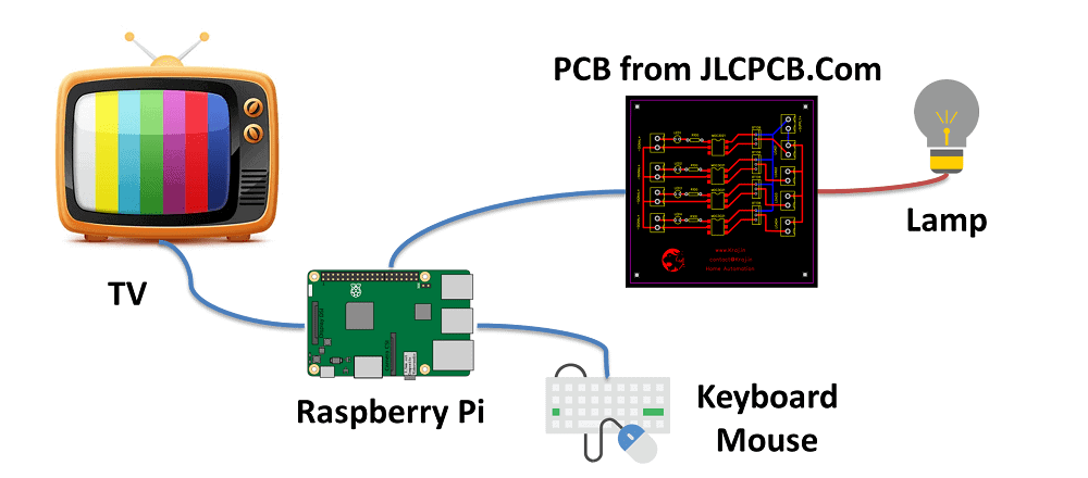
Step 1: Components & Things You Need
- Resistance – 100 ohm
- Led – Any color
- MOC3021 Optoisolator
- Triac – BT136
- AC Two pin sockets
- Raspberry Pi 3 Model B or any other variant.
- Keyboard and Mouse
- HDMI cable
Step 2: Design a PCB
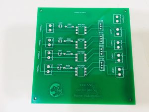
You have to design the PCB from: https://easyeda.com/ or you can use any other PCB design software to build your PCB. Then you have to generate Gerber File.
I have design my PCB and get it done by JLCPCB.
JLCPCB is a Company where you will get 10 no. of 2 layer PCB for just $2 & Big Discount on First order : https://jlcpcb.com.
If you want to get my circuit then contact me at https://www.kraj.in/contact-us/.
Step 3: Connection Diagram
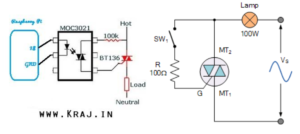
You have to connect all the components as shown in above diagram. Instead of Sw1 in diagram you have to use MOC3021 IC 6th and 4th terminal in series And on primary side pin 1 and 2 goes to your raspberry pi pin 18 and Gnd.
Next just load Raspbian operating system in raspberry pi and follow this steps.
The Code:
You are now ready to write some code to switch the Lamp on. Turn on your Pi and connect HDMI cable with TV.
Create a new text file “LED.py”
Type Following Code in file. Once you have typed all the code and checked it, save and then click on Run button from menu.
Coding
GPIO.setup(18,GPIO.OUT)
print “LED on”
GPIO.output(18,GPIO.HIGH)
time.sleep(3)
print “LED off”
GPIO.output(18,GPIO.LOW)


0 Comments