Theory
| 5A Module | 20A Module | 30A Module | |
|---|---|---|---|
| Supply Voltage (VCC) | 5Vdc Nominal | 5Vdc Nominal | 5Vdc Nominal |
| Measurement Range | -5 to +5 Amps | -20 to +20 Amps | -30 to +30 Amps |
| Voltage at 0A | VCC/2 (nominally 2.5Vdc) |
VCC/2 (nominally 2.5Vdc) |
VCC/2 (nominally 2.5VDC) |
| Scale Factor | 185 mV per Amp | 100 mV per Amp | 66 mV per Amp |
| Chip | ACS712ELC-05A | ACS712ELC-10A | ACS712ELC-30A |
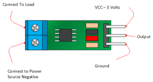
ACS712 Module Pin Outs:
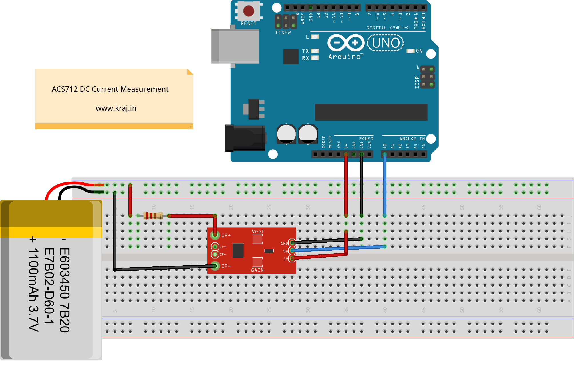
- Always connect load in mentioned direction for positive output.
- If you will connect as illustrated below, the output will be positive ans above 2.5 volt .
- If you will connect it in opposite direction as illustrated in below picture, the output will decrease from the 2.5 volt.
- It will give 2.5 volt when there is no current flowing through it.
Coding
Arduino Acs712 DC Current Sensing
Function: Sense the DC Current and Display on the Serial Monitor
Prepared By: Krishnarajsinh Jadav
Website: http://www.Kraj.in
*/
double Voltage = 0;
double Current = 0;
void setup(){
Serial.begin(9600);
}
void loop(){
// Voltage is Sensed 1000 Times for precision
for(int i = 0; i < 1000; i++) {
Voltage = (Voltage + (.0049 * analogRead(A0))); // (5 V / 1024 (Analog) = 0.0049) which converter Measured analog input voltage to 5 V Range
delay(1);
}
Voltage = Voltage /1000;
Current = (Voltage -2.5)/ 0.185; // Sensed voltage is converter to current
Serial.print(“\n Voltage Sensed (V) = “); // shows the measured voltage
Serial.print(Voltage,2); // the ‘2’ after voltage allows you to display 2 digits after decimal point
Serial.print(“\t Current (A) = “); // shows the voltage measured
Serial.print(Current,2); // the ‘2’ after voltage allows you to display 2 digits after decimal point
delay(1000);
}


How to measure AC current using ACS712 please guide!
Sure I will upload AC current sensing using ACS712.
arduino IDE shows an error that says amp and lt is not declared? help please
Your Error Is Removed. Now copy this new code. Thanks for the correction.
kindly send me the codes/programm for ac current measuring using ACS712 20A
Just go through above link and get coding for AC current measurement.
i want to know the shape of the output wave is it shifted sine wave or what ?
Nop it is nearer to square wave.
I’m still confused about how to use acs712. I have a voltage sensor, and I want to measure a battery lipo power output, so It’s voltage range can reach between 10-12,5 V and the current can reach 0-20 A. So can acs712 read the voltage and current? or I still need to use a voltage sensor?
ACS712 will only measure current. For voltage you have to use potentiometer circuit.
Hi
Can you advise the code to have amps accumulate over time.
if item uses .300 mAh/hr
Time = 180 minutes (using millisec.h)
total current = .920 m Ah based on readings from Analog pin A0 per hour
** either average formula or formula to sum all reading and divide by time..?? ***
thanks, great article too….
Can you help me out to find load resistance connected in series with the ACS712 30A. Power supply 12v.
Because as the resistance changes current also changes.
As you change the load, current will change that is the law of ohm’s.
hi,
What would the code be to add the accumulated Amps over time. minute intervals
thanks
iggi
Hi my name is jatin, and I am working on this kind of project.so may i get your number to call.
If you face any difficulty you can mail at contact@kraj.in
I have tried this diagram with the code you provided. I have compared with a multimeter as well to verify the accuracy. ACS712 provides values which are really not accurate. Or maybe, the code needs to be improved. on my side i use ACS circuit just to identify if there is current or not to get a status of my smart home system.
To have accurate value to calculate power consumption i need to find another way.
Are your home runs on DC?? Because this coding is for DC Current Measurement.
Sir we are connected to DC brushless 12V .14A to this circuit.Kindly tell us how this circuit operates.
I have used many simular formulas and found the accuracy very poor.
Yours seem to be more accurate, however the problem may be with the
ACS712. At zero amps the voltage ranges from 2.5 to 2.68V which not
acceptable. Do you have any idea why this so.
This problem will always occurs with this sensor. No solution out there.
Hy, the voltage that you are sensing is it the voltage on the LED?
It’s current not voltage.
Hy, the voltage you are sensing is it the voltage on the LED?
My sensor pin voltage is 2900 – 2950 instead of the usual 500-512 range, any help?