Theory
Introduction:
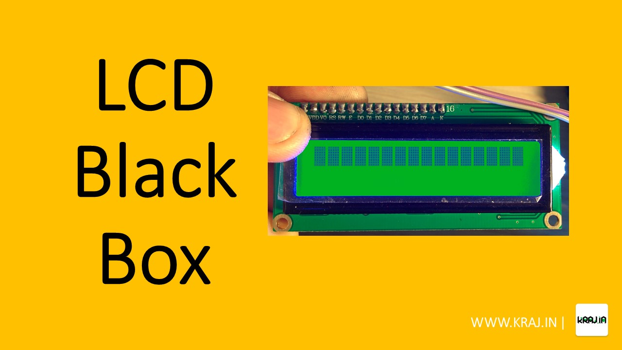
Are you encountering the frustrating issue of black boxes on your 16×2 LCD display connected to Arduino? Don’t worry, we’ve got you covered! In this comprehensive guide, we’ll provide troubleshooting tips to help you identify and fix the problem of black boxes on your LCD display. You’ll learn how to optimize the contrast control resistor, avoid data line issues, and overcome logic voltage incompatibility to get a clear and functional LCD display for your Arduino projects!
Step-by-Step Troubleshooting Tips:
LCD displays are widely used in various electronic projects, but they can sometimes encounter issues that affect their performance. Here are some common problems and their solutions to help you troubleshoot your LCD display effectively.
Display showing black boxes: This issue may arise if you have selected a very low value for the display contrast control resistor. The contrast control resistor, which is connected from pin#3 (VEE) to pin#1 (VSS/GND), should ideally have a value of 4.7K ohms. Additionally, the display may show black boxes even when writing data quickly onto the display. To overcome this, make sure to provide sufficient time delay after sending each character.
Display showing wrong characters: If the display shows incorrect characters despite sending the correct ASCII values, it may indicate a problem with the connection of data lines. This could be due to short circuits between adjacent data lines or improper connections. It is crucial to thoroughly examine for short circuits between adjacent tracks leading to the LCD display.
Display showing totally blank lines: This problem can occur if the contrast control resistor value is set too high. To avoid this, ensure that you have selected a value around 4.7K ohms for the contrast control resistor. If the contrast is set correctly, you should be able to see very light black boxes in the character positions instead of blank lines.
Contrast OK, Delay OK but still no display: If you have set the contrast values correctly and provided the appropriate delay in your code, but the display is still not showing characters, it could be due to a mismatch in logic voltage levels between your controller and the display. LCD displays typically operate at 5V logic levels, so if your controller is powered by a 3.3V or lower power supply, you may need to add strong pull-up resistors (4.7K ohms) to all 11 LCD lines (8 for data, 3 for control). These pull-ups should be connected from the LCD lines to the +5V power supply of the LCD.
By following these troubleshooting tips, you can effectively fix common issues with LCD displays in your electronic projects and ensure optimal performance.


0 Comments