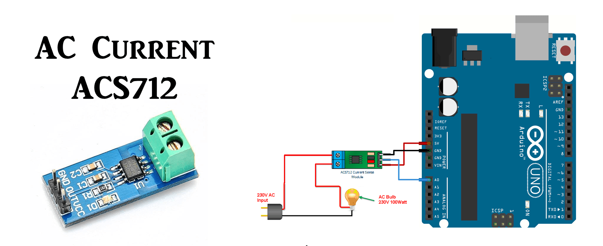
Theory
| 5A Module | 20A Module | 30A Module | |
|---|---|---|---|
| Supply Voltage (VCC) | 5Vdc Nominal | 5Vdc Nominal | 5Vdc Nominal |
| Measurement Range | -5 to +5 Amps | -20 to +20 Amps | -30 to +30 Amps |
| Voltage at 0A | VCC/2 (nominally 2.5Vdc) |
VCC/2 (nominally 2.5Vdc) |
VCC/2 (nominally 2.5VDC) |
| Scale Factor | 185 mV per Amp | 100 mV per Amp | 66 mV per Amp |
| Chip | ACS712ELC-05A | ACS712ELC-10A | ACS712ELC-30A |
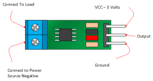
ACS712 Module Pin Outs:
- Always connect load in mentioned direction for positive output.
- If you will connect as illustrated below, the output will be positive ans above 2.5 volt .
- If you will connect it in opposite direction as illustrated in below picture, the output will decrease from the 2.5 volt.
- It will give 2.5 volt when there is no current flowing through it.
Coding
Measuring AC Current Using ACS712
www.Kraj.in
*/
const int sensorIn = A0;
int mVperAmp = 185; // use 100 for 20A Module and 66 for 30A Module
double Voltage = 0;
double VRMS = 0;
double AmpsRMS = 0;
void setup(){
Serial.begin(9600);
}
void loop(){
Voltage = getVPP();
VRMS = (Voltage/2.0) *0.707; //root 2 is 0.707
AmpsRMS = (VRMS * 1000)/mVperAmp;
Serial.print(AmpsRMS);
Serial.println(” Amps RMS”);
}
float getVPP()
{
float result;
int readValue; //value read from the sensor
int maxValue = 0; // store max value here
int minValue = 1024; // store min value here
uint32_t start_time = millis();
while((millis()-start_time) < 3000) //sample for 3 Sec
{
readValue = analogRead(sensorIn);
// see if you have a new maxValue
if (readValue > maxValue)
{
/*record the maximum sensor value*/
maxValue = readValue;
}
if (readValue < minValue)
{
/*record the minimum sensor value*/
minValue = readValue;
}
}
// Subtract min from max
result = ((maxValue – minValue) * 5.0)/1024.0;
return result;
}


Sir we have connected AC axial fan with 220/240v %0/60Hz .14A with switch and voltage regulator to ACS712 30 A circuit IP+ IP – and connected Vout to Arduino A0.Once this program is downloaded we are getting results like .05A IRMS for 0 th postion of regulator, .21A IRMS for 1,2,3,4,5 th postion of regulator.We could not analyse the results.kindly help us in this regard.
Please help, I have tried many different codes but the results are always wrong. Why do I measure the same values when I turn on the lamp when it is off?
I do not care about the precission in the measurementI just need to know if the light is on or off so I can check remotely but I can not get over the problem.
for the tests I am using a led lamp (GU10) 5w 41mA. I tried with the 5A sensor but also with the 30A sensor.
This is the main drawback of this sensor. It give the value even at 0 current. Move on and search other current sensor.
how to measure energy with this
You have to measure voltage also then only you can measure power.
Sir
best coding, while I still not loaded,
but I suppose to imagine that the code will be well.
Yup it’s fine.